Posted on:? Aug 10, 2023| By WayKen Marketing Manager
Metal machining and specifically milling are widespread in modern prototyping techniques. Prototype manufacturers tend to maximize their equipment capabilities in regards to technology. One of the methods that have become popular in recent years is helical milling. Let’s try to clear up what helical milling is about, its pros and cons and how you can use this knowledge while designing your prototype to lower its manufacturing costs.
What Is Helical Milling?
Helical milling is an alternative hole-making process. This process involves an endmill that follows a helical trajectory to achieve a high-quality bore. It offers a lot of advantages compared to conventional drilling and it can downright replace boring machines, which is always advantageous for prototyping shops as they really want to avoid buying lots of equipment.? (Ha, not saying that they are dull, they are quite sharp actually, wait… they are boring and sharp at the same time. This wordplay is killing me). Helical milling can be used to create bores of practically any form, the cutting force is lower, tool wear as well and the achievable quality can be quite high.
Why not drilling?
The main alternative to helical milling is conventional drilling. It is a very widespread method of making holes. Statistically, drilling takes up to 25% of cycle time and 33% of the total number of machining operations when manufacturing a metal part. But why should you consider milling? Despite the fact that obviously, the kinematics are much simpler, drilling has a range of cons that justify using a more complicated milling technique.
For example, Drilling speed differs with the diameter. It is highest at its outer point and is practically zero in the center of the drill ( where the axis is). It means that the machining process near the revolution axis is not actually cutting but plastic deformation. This increases the thrust force of the tool and the tool wears drastically.
Because of the axial thrust force, the drill, especially a worn one, will bend a thin layer of metal as it exits the stock. The resulting leftover material protrudes around the hole and needs to be removed manually. Using a mill instead drastically lowers the leftover material.
Drilling provides awful chip removal conditions.?The processed material can only be removed through the drill flutes. Chip removal influences the surface finish of the hole and the cutting temperature. As the bits of metal move from the cutting zone through the flutes to the surface, they scrape the sides of the hole and lower the surface finish.? It has been proven that the chips carry up to 80% of cutting warmth, so removal problems increase the temperature of the drill. It wears down faster because of that. In order to increase chip removal rate, operators use discrete drilling methods. The drill processes a part of the whole length after which it is removed. This is a good strategy but the drilling time increases.
As you can see, drilling has some significant drawbacks so, in the tendency to increase machining efficiency and thus the efficiency of prototyping shops, manufacturers employ helical milling
Some helical milling specifics
Let’s review some of the processes that happen in helical milling.
Firstly, the end mill moves along a helical path. It means that the milling center must combine the vertical z-axis movement and the horizontal x-y axis. This makes the NC program very complex to write manually, however, a lot of CAM-systems have adopted helical milling as one of the strategies.
The geometry of the chip consists of two zones: the blue one that is created by the side of the end-mill and the red zone that is created by the face of the mill. It has been proved that the ratio between the two zones is determined only by the tool and bore diameters.
With the increase of the tool diameter, increases the blue zone. It provides worse milling in regards to vibration as the blue chip is discontinuous, unlike the red one. So, the WCMT Insert surface finish will be worse.? In addition, with the increase of the volume removed by the side of the mill, radial cutting forces grow (red Fr at the picture) and they bend the tool inside of the hole, so the tolerance decreases.?The negative effect is decreased to some degree by the fact that larger tools have more rigidity.
If the tool is smaller, the red zone prevails, so the radial force is small, as well as vibration, however, the decrease in tool diameter is limited by the system rigidity.
I’d say that using a larger tool at first is better and changing it to a smaller one for a final cut with low depth and feed will result in a great surface finish.
Reasons to use helical milling
As you can see, helical milling is a promising process that offers a number of Indexable Inserts advantages.
You can achieve any diameter with better precision and surface quality without changing the tool.? If you’ve ever drilled a whole bigger than 35 mm, you’ll know that doing it with only one drill is a bad decision. It’s usually done with a range of smaller drills, For example, the initial whole will be 10 mm, then it will be drilled to 20 mm with a bigger drill and only then to 35 mm. Afterward, if you need more precision or surface finish, you ream or countersink the hole. That’s like 4-6 tool changes to get a whole did. Well, with helical milling you’ll just need to use one endmill to cut out the hole and then use a smaller feed to achieve desired tolerance and quality. You can achieve up to IT7 with Ra 1,25 without changing the tools.
You have a lower cutting temperature and better chip removal. The endmill does not take up the whole space of the bore. That’s the main advantage. You don’t have to extract the tool after plunging every 30 mm or so. Just spray the coolant into the hole and it will delete the chip and lower the temperature of the machining.
You can predict tool wear and make trajectory modifications. One of the main problems in drilling is that when the drill is worn, you can mostly see it once it is completely broken when machining hard materials, it can even get stuck in the bore. With helical milling, you are basically just milling. So, you can predict tool wear by using standard calculation methods or using tool life specified by the manufacturer. You can even take those changes into account during the process. So, you can change the trajectory a bit to preserve the diameter dimension. You can’t really do that with drilling though. Oh, by the way, the tool life is determined by the face wear of the tool (red zone chip).
Conclusions
Of course, helical milling is an innovative process and it has its cons. For example, its chip removal rate isn’t as fast and its parameters are not that well researched yet. However, this technique lowers the number of setups, machining, and tooling, while retaining the quality of the bores. That is a?considerable advantage for prototyping manufacturers who want to minimize the amount of tooling and equipment required.
The Carbide Inserts Website: https://www.estoolcarbide.com/product/vnmg-carbide-inserts-for-stainless-steel-turning-inserts-p-1188/
These 100x magnifications of a 20-rms surface finish produced in identical CD650 workpiece materials show the difference between the effects of a standard power supply (left) and an AE power supply.
With a standard power supply on a wire EDM, stray energy from the cutting process (signified by the glowing light bulb) interacts with contaminants in the dielectric fluid, producing charged particles, shown in red, that attack the cutting edge as well as the top and bottom of the workpiece.
With an AE power supply on a wire EDM, stray energy from the cutting process is eliminated or controlled (signified by the unlit bulb), so there is little or no interaction with contaminants in the dielectric fluid. Particles, shown in white, do not attack the workpiece.
PreviousNext
These problems were intrinsic to the early days of EDMing and continued up through 1990. In 1991, the first compensating power supply circuitry was used for fine finishing on the skim cuts.
Previously, rough cutting was done with DC power for maximum speed and material removal. Fine or skim cutting was then done, at different power settings on an AC electrolysis-limiting power supply, to finish the dimension and, most often, to cover the damage done to the work-piece in roughing.
A true anti-electrolysis (AE) power supply can be used for rough and skim cutting, thus minimizing surface degradation, the material’s susceptibility to rust and corrosive action, plus the overall improvements in accuracies and total time required to finish parts.
Since the mid-80s, literally all EDM manufacturers have addressed the finishing power supply issue, with various solutions offered. This is in sharp contrast to the “early” days of EDM’s promotion, when speed, speed and more speed were the goals.
Briefly, let’s get back to the basics of this critical aspect of EDMing.
What Is Electrolysis?
For the practical application of EDM, electrolysis is the production of chemical changes by the passage of an electrical current through an electrolyte, that is, a nonmetallic electrical conductor through which current is carried by the movement of agitated ions.
In wire EDMing, stray energy in the dielectric fluid, produced by the cutting process itself, interacts with contaminants in the flushing fluid to disrupt the surface of the workpiece.
The chief result of this process in all materials is an increased heat-affected zone, or white layer, on the surface. Depending upon the workpiece material being cut, the visible results of this action will vary, as described above.
The current-carrying EDM wire commonly discharges particles as well as produces the cutting action on the workpiece. The stray current, once thought inevitable, causes detrimental surface effects such as:
bluing of titanium,cobalt binder depletion of carbide,anodic oxidation of aluminum,rusting of ferrous materials, andeventual micro-cracking of all materials.
This last effect had prohibited increased use of wire EDMing in medical, aerospace, aircraft and ordnance applications because that condition would render parts either unsafe or inoperable to the specifications required.
Meeting The Challenge
Thus, the challenge facing EDM builders was to engineer a power supply that would minimize, even eliminate, the interaction of the stray current and contaminants on the workpiece surface. Various builders have taken various tacks to solving this problem. Mitsubishi EDM, for example, combined voltage modulation, advanced transistor pulse circuitry and state-of-the art sensors, plus software improvements to interface the cutting program and actual condition protocol, to develop its patented AE power supply. This combination of technologies indicates the complexity of the problem and the effort required to make progress in this area. However, the benefits are substantial–so substantial that this same builder has made its AE power supply standard equipment on its new X Generation wire EDMs.
Other methods are available, many of which have excellent characteristics, as they all aim at two important goals: namely, to eliminate or dramatically reduce surface degradation while, simultaneously, maintaining productivity on the machine.
Depending upon the EDM wire being used, brass or coated, surface finishes down to 0.5-mm Rmax are now attainable with no significant loss in speed. Doing certain types of wire work will always put a premium on an operator’s work rate, and only the individual shop’s particular needs can dictate the optimum conditions that should be employed.
However, unlike in the past, EDMers now enjoy more choices and thus fewer compromises when balancing speed versus accuracy and finish. To some extent, largely as the result of better power supplies and control circuitry, shops really can “have it all,” or close to it.
The Differences AE Makes
Comparing the surface integrity achievable with and without an AE power supply makes it clear that several electrochemical conditions are occurring on an AE-equipped machine:
Pitting, which occurs with conventional power supply technology, is virtually gone.The heat-affected zone is drastically reduced.Surface corrosion is minimized on all materials.
The net effects of this AE power supply to the typical tool-and-die shop or mold maker are these:
Longer carbide tool life because of less cobalt depletion.Longer steel tool life because of less white layer and surface corrosion.Faster and fewer skim cuts needed to finish any part.Less polishing time and attendant cost because of less surface degradation and better finish out of the tank.
When used in conjunction with the Cemented Carbide Inserts fine finishing circuitry currently available, a true AE power supply can enable wire EDM to tackle the most demanding jobs, ones never thought possible. Clearly the evolution of EDM has been accelerated by the development of anti-electrolysis power supplies, another reason why wire EDM is now considered a viable method for an ever-widening spectrum of jobs in all areas of industry.
Click here to learn more about supplier MC Machinery Systems, Inc..
Reports From The Real World
One of the first builders to introduce anti-electrolysis (AE) technology, Mitsubishi EDM has had wire machines equipped with AE power supplies in the field long enough for interesting case histories to be gathered. A sample of these indicates the impact that AE technology will have on the typical EDM user.
Chris Shoulder Milling Inserts Gendusa, who runs the EDM operation at Custom Stamping in Covina, California, told his story. “The way we made punches and dies a few years ago seems to be on the decline. We do less and less grinding now. Instead, we use a wire EDM with the AE power supply and experience no recast whatsoever, plus all the micro-cracking problems we had are gone. Typically, we run a variety of micro-grain tungsten carbide, A2/D2 tool steels and some powdered metals. Thin steel frames are stacked and left in the tank for overnight cutting, maybe 18 up to 24 hours. We know the rust would be a problem with that kind of dwell time.
“Other advantages are in the taper and radius dimensioning, where we once needed to dress a grinding wheel and take a lot of time to do the work. All our die work goes to our company stamping plant in Carson City [Nevada], and we’ve already seen dramatic increases in wear life. We attribute most of that to the AE power supply on our wire EDM.”
As for the speed of cutting when using an AE power supply, Pete Grisel of Magnum Diamond in Rapid City, South Dakota, said this: “We do high-precision parts for eye, medical, surgical and other equipment. Typically, we run titanium, stainless 317 and some aluminum. We’ll stack our thinnest materials, 0.010-inch 440C stainless, 45 high and cut them in 35 minutes, with ¤0.002-inch accuracy, at 500 pieces per day. We also get a 7 to 8-rms, nearly mirror finish on a corneal shaper we produce.” Magnum Diamond, a division of the Chiron Corp., has been running their AE power supply for over two years.
At EDM Labs in Fremont, California, Frank Wenzel runs an AE power supply on a wire EDM used to cut titanium 6AL-4V into an extremely delicate medical device component. “Titanium usually blues, and that problem simply went away with AE. Of course, it’s not just cosmetics involved here. This power supply completely eliminated the embrittlement problem, and it’s faster. We cut titanium faster with 0.008-inch diameter wire on an AE-equipped machine than we did with 0.01-inch wire before. Even on 50 pieces, that’s a big difference.”
Another job at EDM Labs involved a very tight cut into a 0.3-inch-high web of titanium material, using 0.004 wire. The part to be formed was 0.0013 inch thick, +0/-0.0003 inch, flat to within 0.0001 inch. “It simply would have been a nightmare to do this job before AE,” according to Mr. Wenzel.
For shops where multiple part cutting was usually avoided due to rust build-up on conventional tool steels, no such concern is necessary with AE, reports indicate. Ejector pinholes, for example, can be machined into polished mold cavities without compromising the finish. Mold shops can actually use less expensive materials and get the same results. Less stainless is needed because of the rust avoidance issue. This means that less expensive S7 and H13 steel can be used for molds that are designed to be wire-cut instead of the more expensive 400 series.
At every stage of a technology’s evolution, there are always roadblocks to its advancement. In the rapid development of EDM (electrical discharge machining), no hurdle has been more difficult to overcome than the one that is most basic to all machined metal surfaces in a liquid environment: Dissociation of ions caused by electric current passing through the solution, otherwise known as electrolysis or, in the common parlance, rust. Every metal subjected to EDMing is vulnerable to this condition, from the basic tool steels to the most advanced alloys and composite materials.
Electrical discharge machining, as the name implies, creates a certain amount of stray current in the dielectric fluid, by definition. Literally, the instant such current interacts with any contaminants in the solution, surface degradation on the workpiece begins.
Titanium will begin to turn blue, an action caused not by heat, as some suspect, but electrolysis. Aluminum undergoes an anodic oxidation. All iron-based materials simply begin to rust. Sintered materials such as carbides suffer surface degradation, the result of cobalt binder depletion.
The Carbide Inserts Website: https://www.estoolcarbide.com/product/dnmg-carbide-inserts-for-stainless-steel-turning-inserts-p-1185/
Tungsten carbide powder (WC) as a black hexagonal crystal with a metallic luster, a dark gray powder, the hardness close to diamond, is the main raw material for the produce Carbide milling inserts tungsten carbide. Its physical characteristics are as follows: chemical formula: WC, melting point: 2870 ℃, boiling point: 6000 ℃, the relative density of 15.63 (18 ℃), it does not dissolve in water, hydrochloric acid and sulfuric acid, easily dissolved in mixture acid of nitric acid and hydrofluoric acid which is a good conductor of electricity and heat. Tungsten carbide is fragile, if adding a small amount of infiltration of titanium such as cobalt, titanium and other metals can reduce brittleness, but also make the tungsten carbide used in more areas. Using tungsten carbide as steel cutting tools used often adding titanium carbide, tantalum or they mixtures in order to improve the anti-knock capacity.
Tungsten carbide powder may be dissolved in a variety of carbide, especially in titanium carbide forming solid solution Tungsten Steel Inserts TIC-WV. Another compound of tungsten and carbon is tungsten dioxide carbide, the formula W2C, a melting point of 2860 ℃, boiling point of 6000 ℃, the relative density of 17.15, while its properties, preparation method, use of tungsten carbide powder and similar.
Tungsten Manufacturer & Supplier: Chinatungsten Online -https://www.estoolcarbide.com
Email: https://www.estoolcarbide.com
Tungsten & Molybdenum Information Bank: https://www.estoolcarbide.com
Tungsten News & Tungsten Prices, 3G Version: https://www.estoolcarbide.com
Molybdenum News & Molybdenum Price: https://www.estoolcarbide.com
The Carbide Inserts Website: https://www.estoolcarbide.com/product/vbmt-steel-inserts-cnc-lathe-turning-p-1205/
Copper remains one of the oldest metal materials. That’s not at all surprising considering the exceptional properties of copper materials. More specifically, copper has excellent corrosion resistance and thermal and electrical conductivity. Thus, making them valuable for several applications.
CNC copper machining is one of the most precise metal machining services employed in various industries for fabricating copper parts. Yet, there are several considerations associated with copper parts machining.
This guide examines all you need to know about CNC copper machining, its applications, and the various factors to consider before machining copper.
Computer Numerical Controlled carbide drilling inserts (CNC) machines are among the most sought-after manufacturing technologies employed for machining applications. This is due to their high speed, accuracy, precision, and compatibility with various materials.
Above all, this machining service has become very common in manufacturing various materials into desired parts, and copper is no exception. Previously, machining copper was tedious due to its high flexibility, toughness, and plasticity.
Still, CNC machining has made copper parts machining much more manageable. This is all thanks to the automated processes involved in machining desired copper parts.
Copper materials are one of the major groups of commercial metals. To a large extent, you’ll find that different grades of copper materials are available for copper part machining. Also, they comprise varying properties suitable for specific machining projects.
Hence, choosing the right material for your machining project can get tricky as it involves several factors.
Even so, identifying the material with properties suitable for your copper parts is the first step to employing machining.
Take a look at the different grades of copper materials for CNC machining below:
Pure copper materials are usually soft and malleable. The dilute grade of pure copper contains a small amount of various alloying elements. Hence, this helps alter one or more fundamental properties of pure copper to desired forms. Likewise, adding other alloying elements to this copper grade increases their toughness.
Commercial pure copper grades contain about 0.7% total impurities in their composition. You’ll discover that they are designated by UNS numbers C10100 to C13000 based on the added elements and impurity level.
Pure copper is most suitable for manufacturing electrical equipment. They include wiring and motors. Also, this copper grade applies in industrial machinery such as heat exchangers.
Electrolytic tough pitch copper originates from cathode copper. Cathode copper means copper refined using electrolysis.
Generally, the process involves filling copper compounds into a solution. Then applying adequate electricity helps purify the copper material. As a result, most electrolytic copper contains lesser impurities than other copper grades.
You’ll find that C11000 is the most prevalent of all electrolytic copper grades. C11000 usually contains less than 50 parts per million metallic impurities, including sulfur. Furthermore, they have high electrical conductivity, up to 100% IACS (International Annealed Copper Standard).
Their exceptional ductility makes them suitable for electrical applications. They include windings, cables, wires, and busbars.
Compared to other copper grades, oxygen-free coppers have the highest purity. They also contain little to no oxygen content. In most cases, oxygen-free copper grades include many high conductivity electrical copper components. Yet, C10100 and C10200 are the most common.
- C10100, known as Oxygen-free electronic (OFE), is a pure copper with about 0.0005% oxygen content. More so, it is the most expensive of these copper grades.
- C10200, also called Oxygen-free (OF), contains about 0.001% oxygen. It also has high electrical conductivity having at least 100% IACS, which is no better than electrolytic copper materials.
These oxygen-free copper materials get manufactured by induction melting using high-quality cathode copper. In this manufacturing process, cathode copper gets melted under non-oxidizing conditions provided by graphite bath covering. Thus, this helps reduce the hydrogen content in the working atmosphere.
Oxygen-free coppers are most suitable for high vacuum electronics due to their high conductivity. They include transmitter tubes and glass-to-metal seals.
This copper material comprises various alloying elements. The notable elements include nickel, tin, phosphorus, and zinc. The presence of these elements helps increase the machinability of this copper grade.
Furthermore, free-machining copper materials comprise copper alloys such as bronze and brass. Take note of the following:
- Bronze is an alloy of copper, tin, and phosphorus well-known for its hardness and impact strength.
- Brass is an alloy of copper and zinc with exceptional workability and corrosion resistance.
Free-machining copper materials are suitable for a wide range of copper parts machining. They include coins, torches, machined electrical components, gears, bearing, automotive hydraulic, etc.
Most CNC copper parts available today have specific benefits and drawbacks. Check them below:
Generally, most CNC copper parts have good machinability, ductility, and impact strength. They also show a high thermal and electrical conductivity, corrosion, and wear resistance
Another benefit of CNC machining for copper parts encompasses good formability in both hot and cold processes. Aside from this, CNC copper parts are compatible with several cost-effective surface finishes.
Despite the all-around pros, some drawbacks are associated with machining copper parts with CNC. For instance, not all copper materials can undergo processes like spot welding, coated metal arc welding, etc.
Moreover, different copper grades have varying corrosion resistance properties. Thus, some CNC copper parts are susceptible to corrosion in atmospheres with reactive substances.
CNC copper parts continue to drive popular demand. Even so, there are some vital factors to consider before copper part machining. Take a look at some of these factors below:
Before CNC copper machining, you must select the correct grade of copper material most suitable for your application. For instance, choosing pure copper to manufacture mechanical parts is inappropriate and expensive. As such, the excellent machinability of free-machining copper makes it most suitable.
Besides, they are also cost-effective. So, you must examine the properties required for your copper parts to select the correct copper grade for machining.
You must also address the design requirements and specifications before machining copper. This will help you achieve the functionality needed for your manufactured copper part.
A rule of thumb is that it is best to use and maintain a wall thickness of 0.5mm to manufacture aesthetic copper parts.
Furthermore, you can also engage in some design best practices. They include reducing the number of parts setups, dimension checks, and preventing deep pockets with small radii.
Feed rate is the speed at which the cutting tool engages the workpiece. Hence, you must set the correct feed rate before copper part machining because it impacts the copper part’s quality, life span, and surface finishes. Moreover, copper conducts heat quickly. So, a high feed rate can increase tool wear over time.
Many copper grades have varying machinability and solidity. Thus, selecting the suitable tool material for copper part machining remains essential. Moreover, you’ll find that CNC steel machining applies in manufacturing high-speed cutting tools used in machining copper. This helps prevent complications like tool wear and tear and chip formation.
As the name implies, surface finishes are processes after manufacturing metal parts. Generally, these post-processes aim to alter the surface of the copper parts to get specific properties and make them more appealing.
Below are the standard surface finishes applicable to copper parts.
During electropolishing, a microscopic layer of material gets removed from the surface of copper parts. This material typically ranges between 0.00254mm to 0.0635mm in width. As a result, this post-processing method aid in making the surface of your finished copper part smoother and glitterier.
Further, electropolishing can help improve the corrosion resistance of finished copper parts.
Copper electroplating helps further protect your copper parts’ outer surface from oxidation. The metal plates get implemented without disrupting their electrical and thermal conductivity. Thus, this process helps prolong the longevity of your copper parts.
This post-processing method helps cover the flaws in your manufactured copper parts. Also, bead blasting creates a durable, duller, and more subtle finish.
Several metal machining services are employed in many industries for producing metal parts, but some machining techniques are only suitable for certain metal materials. You’ll agree that pure copper machining can be more challenging than brass machining.
As a copper alloy, brass contains other alloying elements such as zinc, making it much easier to machine than most metallic materials. As such, you can machine copper alloys using various techniques.
Check out some of the suitable techniques for copper parts machining below:
CNC milling is an automated machining process that controls rotary cutting tools’ movement and feed rate. Thus, in CNC milling copper, the tools rotate and move across the surface of the copper materials. Then, the excess copper materials are slowly removed until the needed shape and size gets formed.
CNC milling is most common with copper alloys as they have better machinability and produce precise and intricate parts. Manufacturers often use the 2-flute carbide end mill for copper milling.
Furthermore, experts use this process to fabricate diverse design characteristics for copper parts. They include notches, pockets, holes, slots, grooves, flat surfaces, contours, etc.
This manufacturing process requires affixing the copper materials in a position. More so, the cutting tools fed to the workpiece remain stationary. Hence, the turning copper material at the proper set speed reduces in size to the desired dimension.
Turning is adaptable for many copper alloys and permits the rapid manufacturing of high-precision copper parts. Besides, this process is also cost-effective. Thus, CNC turning copper is suitable for making many electronic and mechanical components such as electrical wire connectors, valves, bus bars, radiators, etc.
Copper CNC parts are valuable in several industries, including electrical, construction, transport, and consumer goods companies.
Below are the applications of copper CNC machining:
- Heat exchangers
- Electrical connectors
- Radiators
- Bearings and gears
- Gas welding nozzles etc
CNC coppers parts are suitable for many different applications today. Yet, quality copper machining services are pivotal to meeting the design specification and requirements for these copper parts.
At WayKen, we have experienced professionals that can handle all your copper CNC machining services. We boast top-notch CNC milling and turning copper techniques to meet your specific product design.
Contact us today for one-on-one support service, and you will get a response within 12 hours.
What is the cutting speed for copper?
You can apply different cutting speeds for copper materials. But note that this depends on the copper grade and the machining method. For instance, a standard cutting speed of 2000 to 4000 fpm gets applied when milling brass
Is copper easy to mill?
The ease of copper milling varies based on the grade of copper material you are working on. You’ll find that pure copper is a complicated metal to machine due to its high plasticity and toughness. In contrast, copper alloys like brass are much easier to mill due to their improved machinability.
Which alloying element in copper is suitable for high-speed machining?
Alloying copper with elements such as zinc, tin, nickel, aluminum, and silicon improves the machinability of copper. Hence, this makes it suitable for high-speed machining.
The Carbide Inserts Website: https://www.estoolcarbide.com/
In recent years, aluminum extrusion has remained an essential aspect of product innovation and production. It is a significant part of our daily life as manufacturers use this process to make different components for homes, workplaces, and many more.
Even though extruded aluminum parts are used everywhere, many people hardly notice them. Aluminum extrusion has various applications in various industries due to its remarkable features. This article will discuss aluminum extrusion, its techniques, advantages and disadvantages, and key considerations for extrusion design. Let’s get to it!
Aluminum extrusion involves heating and pushing aluminum alloy through a die with a predesigned cross-sectional shape. A firm ram pushes the aluminum through the die and pulls it along a runout table during the operation. Usually, you can modify the die’s opening to create several shapes and sizes that meet your product specification.
This process is a straightforward technique; it is easy to understand on a fundamental level. The force involved in aluminum extrusion is similar to that used when you compress a tube of toothpaste with your fingers. Also, the extrusion die has a similar function to the opening of the toothpaste tube. The extrusion comes out as a long solid extrusion because the opening is a solid circle.
There are two main aluminum extrusion techniques – Direct and Indirect extrusion.
This is the most commonly used extrusion aluminum technique. The aluminum extruder places the billet/heated aluminum in a container with heated walls while a moving ram pushes the metal through the die opening with force. This step produces a high amount of pressure.
In addition, machinists usually put material blocks between the heated aluminum (billet) and the ram, preventing them from coming in contact. Most suppliers and manufacturers call this technique a direct/forward extrusion process because the aluminum and the ram move forward in the same direction.
Indirect or backward extrusion is entirely different from the direct technique. In this process, the heated aluminum and the container move concurrently while the die remains in the same position. Machinists often use a “stem” to perform this operation. The length of the stem must be longer than the container’s length. Hence, the stem forces the aluminum billet through the stationary die.
The backward extrusion generates less friction compared to the direct extrusion technique. It has a better heat control feature. This outcome may be a result of the applied force, which is relatively steady. Also, the consistent temperature ensures better grain structure and mechanical characteristics. As a result, the product quality for indirect extrusions is typically dependable.
The aluminum extrusion process has limitless capabilities regarding shapes available in various specifications and sizes. Extrusion is integral to several industries; this makes it pretty challenging to list all its types. The main categories of extrusion include:
- Hollow Shapes: shapes such as tubes or profiles with varying cross-sections (i.e., rectangles, circles, squares, etc.)
- Semi-Solid Shapes: such shapes include channels, angles, and other partly opened shapes.
- Solid Shapes: This includes solid bars and rods with different cross-sections. (i.e., squares, circles, rectangles, etc.)
- Custom Aluminum Extrusion Shapes: These types of shapes usually have multiple extrusions. Also, they could be interlocking shapes with several color profiles. These shapes are precise to the designer’s specifications.
The first step is to make a round-shaped die or use an existing one if available. Preheat the die to precisely 450-500?C before initiating the extrusion process. This helps to ensure that the metal passes through evenly and maximizes the die’s longevity. You can load the die into the extrusion press after the preheating procedure.
The next thing is to cut the cylindrical billet from a stretched log of material, then preheat the billet in an oven to 400-500?C. This technique prepares the billet, making it malleable for the operation. It ensures that it is not molten.
Transfer the billet into the press mechanically after preheating it. However, add lubricant to it before filling the billet into the press. In addition, ensure to put a release agent to the extrusion ram. Consequently, this helps to prevent the billet and ram from joining together.
At this point, the malleable billet is ready in the extrusion press. Here, the hydraulic ram can apply precisely 15,000 tons of pressure. This pressure forces the malleable billet into the container. The aluminum material stretches till it fills the container’s walls.
The aluminum material that fills the container’s walls gets pressed against the extrusion die. You need to apply pressure to the material continuously. Hence, the extruded material emerges through the die opening fully formed.
A puller grasps the extrusion, holding it in place after exiting the press. It safeguards the extrusion as it leaves the press while the alloy undergoes a “quenching” process as it moves along the table. The profile cools off evenly with a full water bath or fan.
Once the aluminum extrusion makes the total table length, use a hot saw to shear it. However, note that temperature is essential at each step of the extrusion method. Despite the quenching process, the extrusion is not always fully cooled off yet.
After completing the shearing process, move the extrusions to a cooling plain from the runout table. The profiles remain there till they achieve room temperature. As soon as they reach room temperature, stretching begins.
At this stage, you will discover certain twists in the shape of the extruded aluminum that needs correcting. It would help if you had a stretcher to repair these twists. Hold each profile manually at different ends while pulling them till they are entirely straight. This procedure helps to adjust the extrusion to the desired specification.
At this stage, when the extrusions are fully straightened and work hardened, you can now move them to the saw table. The next thing is for you to cut the extrusions into desired lengths. These lengths are usually between 8-21 feet. Move these extrusions to the oven for aging to the proper temper (T6 or T5) after completing the sawing process.
Upon completion of the extrusion process, you can enhance the properties of these profiles by treating them with heat. After the heat treatment, consider fabricating the extrusions if there are dimensions that need correction. In addition, adding surface finishes helps to enhance the aesthetic appearance and corrosion resistance properties of the extruded aluminum.
Although the above-explained extrusion steps of the aluminum extrusion process may appear easy and automated, these steps can be very complicated. The extrusion process is quite complex and depends on the relationship between numerous parameters that must be managed. They include the following:
In general, the extrusion speed is directly proportional to the?temperature inside the container and the metal pressure. To maintain a stable process and provide a constant extruded segment, the speed,?temperature, and pressure?must be suitably correlated.
Any shape’s extrusion ratio is an?indicator of the amount of?mechanical work that?will be done during the?extrusion process. When the extrusion ratio of a section is relatively?low, there will be minimal?mechanical work on the areas of the shape involving?the largest metal mass. When the extrusion ratio is high, on the other hand, more pressure is required. The pressure is to?force the metal through small?openings.
The ideal billet temperature provides suitable surface conditions and?acceptable tolerances. Likewise, it ensures the shortest possible cycle time. It is always preferable to have the lowest possible?temperature for the billet extrusion. Too high temperatures will cause the metal to flow more freely. The metal might resist entering confined areas. Thus, the shape dimensions may fall outside of the specified tolerances. Similarly, high temperatures can cause the metal to rip at?thin edges and sharp corners.
Weight per foot becomes important in the extrusion of aluminum due to the different extrusion presses. Extruding lighter portions, as expected, requires smaller presses. However, there are also other issues that may necessitate larger capacity presses.
A common example is a bigger, thin-walled hollow extrusion shape. Despite having a low weight per foot, the extrusion press tonnage required may be greater. The effect is similar to that of the extrusion ratio. A higher factor makes the part more difficult to extrude. As a result, this has an impact on press production.
The shape determines the complexity and costs of extruding a component. The aluminum extrusion process?can create?a wide variety of shapes, but it has some restrictions. Simple solid shapes, for example, will be considerably easier,?faster, and less expensive?to extrude than semi-hollow shapes. The more complicated the shape, the more difficult and expensive it is to extrude.
After the successful completion of the extrusion and quenching processes, you also need to carefully and closely monitor these parameters:
- Dimensions and tolerances of the product
- Macro-structure of the bars/tubes/profiles
- Surface finish
- Mechanical properties
- Other special quality considerations
The post-treatment options for extruded profiles help to improve their properties. These are some of these options:
To improve their ultimate tensile strength and yield stress, you can heat-treat aluminum alloys in the 5000, 6000, and 7000 series. To do this, you must put these profiles in ovens where they are quickly aged.
Mechanical machining of extruded aluminum is not a single process; it involves a collection of methods that help enhance the aluminum extrusion’s surface. These include cutting, polishing, sanding, and grinding. Unlike chemical applications, you have to use abrasive media to apply mechanical force to the surface of the aluminum to smoothen it. It helps to enhance its surface in preparation for another finishing operation.
Aluminum bars can take different finishing treatments. This helps to enhance the appearance of these extruded profiles and their corrosion properties.
●Anodizing
Anodizing is a process that helps strengthen the aluminum’s naturally-existing oxide layer. It does this by improving its corrosion resistance properties. Also, anodizing aluminum makes the metal more resistant to wear, strengthening the surface emissivity and creating a porous surface that can accept various colored dyes.
●Painting
Manufacturers often paint extrusions for aesthetic reasons. However, it also helps to increase its longevity and reduce the cost of maintenance. You can also apply different colors to extruded aluminum profiles, providing a buffer against corrosion.
●Blasting
Blasting helps to eliminate residue and scale present on a machined component after heat treatments. This procedure helps to add texture to the surface while removing other contaminates that may remain after heat treatment. Blasting helps to make further operations, such as machining carbide milling inserts and painting, easier, giving your extruded aluminum profiles an aesthetic matte finish.
Most manufacturers prefer the aluminum extrusion process to other production processes because of their extraordinary combination of toughness and lightness. However, aluminum extrusion has more advantages from the industry perspective. Here are some of these advantages:
- Extruded aluminum is typically rigid and stronger.
- Low industrial cost.
- High flexibility of operation.
- They are usually an economical and competitive manufacturing option for handling complex cross-sections.
- Extruded products have a perfect surface finish and are stronger than those made using cast aluminum.
However, it is essential to note that aluminum extrusion has some disadvantages despite its enormous advantages.
- Aluminum extrusions are generally limited by the capacity of the steel container on the extrusion press.
- The extrusion die is often subjected to harsh working conditions like high temperature and friction, making it easily worn out. This generally affects the strength and lifespan of the mold.
The material qualities render aluminum extrusion an effective and efficient manufacturing process for many industries. The material’s tensile strength and strength-to-weight ratio make it perfect for extruding transmission housings, chassis for vehicles, engine blocks, and many other essential parts.
Extruding aluminum plays a vital role in producing nuclear reactors, cooling devices in electronics, air conditioners, and condenser tubes. Extruded aluminum has non-magnetic properties making them suitable for house wires, coaxial cables, and aluminum enclosures.
In addition, this aluminum material’s corrosion and rust-resistance properties make it ideal for outdoor applications. It is important to note that aluminum extrusions have high reflective properties. As a result, they are excellent for shielding products from infrared radiation, light, and radio waves.
If you need a reliable manufacturer to help you manufacture low-volume extruded aluminum parts, WayKen is the right shop to visit. We offer high-quality aluminum extrusion fabrication for quality components with excellent corrosion and wear resistance properties.
Our team of professional engineering and advanced technology make us deliver custom aluminum extrusion and other aluminum machining services. Also, we offer various surface finish options for your final products. Just Contact us today and let WayKen meet all your machining needs.
Aluminum extrusion is an economical production process that helps to fabricate different products with varying shapes. This process helps manufacture different simple or complex shapes with excellent product properties. You can create 8-24 foot long profiles which can be fabricated, heat-treated, and given finishing options to best fit your product specification. However, you should follow the extrusion steps and design tips carefully to get the best results.
Which aluminum alloys are suitable for extrusion?
The aluminum 6063 is ideal for the extrusion process. However, the 6061 is usually stronger. So, if strength is a primary requirement for an application, the 6061 is the suitable choice between the two.
What factors affect aluminum extrusion costs?
The critical factors influencing the aluminum extrusion costs are die and tooling costs, current aluminum costs, labor and production costs, surface finishing and secondary operations, and production volume.
Which aluminum is better for extrusion between 6061 and 7075 aluminum?
Both aluminum alloys are suitable for extrusion as they are heat-treatable. The 6061 aluminum is better for extrusion due to its high thermal conductivity. Although the 7075 is much stronger than the 6061, it melts quickly at a lower temperature.
The Carbide Inserts Website: https://www.estoolcarbide.com/pro_cat/steel-inserts/index.html
Milling is a form of subtractive manufacturing that involves cutting a stationary flat surface with a rotating tool. Climb and Conventional milling are the two main ways machinists use for milling a part. However, choosing between them is often challenging as both have merits and demerits.
Here, we examine the differences and the advantages and disadvantages of conventional milling and climb milling. We also provide factors to consider when choosing between them for milling to help you make the right machining decisions.
Also known as down milling, this refers to a milling process where the cutting tool and the workpiece rotate in the same direction. One advantage of climb milling is that there is zero chance of recutting. The reason is that the cutting tool’s teeth climb onto the workpiece during milling, depositing the cut chips behind the cutter. It is important to note that chip formation in this milling process starts with a full thickness, but as the cut progresses, the thickness decreases along with it.
This is the traditional CNC milling process, where the cutting tool rotates in an opposing direction to the workpiece. Also called up milling, cutting in conventional milling occurs in an upward direction.
As opposed to Climb milling, chip formation in conventional end milling starts from zero and gradually increases. Furthermore, the cut chips stay on the path of the cutter due to their upward rotation.
What is the difference between conventional and climb milling? Well, many differences exist between them, from process to result. However, tool deflection affecting cutting accuracy is a major difference between these two milling methods.
Regarding tool deflection in conventional milling, it is parallel to the cut, which translates to greater control over the cutting process and a lower margin for error. On the other hand, tool deflection during climb milling is usually perpendicular to the cut. This direction may decrease or increase the width of the cut, affecting its accuracy.
When roughing a workpiece, the recommendation is to try climb milling, which yields a faster result. Also, during roughing, the tool deflection effects on accuracy are negligible, as the finish pass would make the workpiece more accurate.
Both processes have their advantages, depending on the application. Let us examine these advantages as they may influence your choice of which method suits your workpiece best.
Better Tool Life
The cutting tool used for this process often has better service life than the ones used in conventional milling. The reason is that the tool does not undergo much stress during the cutting process. A mill cutting tool used for climb milling often experiences lower heat generation and deflections than conventional milling. This results in less wear, with the tool living up to 50% longer than that used for conventional milling.
Improved Surface Finishing
Since the chip thickness decreases as the climb milling process progresses, it results in fewer deflections during the cutting process. Besides, cutting in this process deposits the chips behind the cutter, eliminating recutting and guaranteeing an excellent finish to machined parts.
Low Cutting Load And Heat Generation
There is lower heat generation during climb milling because of the gradual reduction in chip width as cutting progress. Also, since the cutting force is downwards, there is a reduction in the overall cutting load and workpiece holding requirements, especially during horizontal milling processes. The downward force exerted by the cutter may also help eliminate machining chatter as it keeps the workpiece tightly against the surface beneath.
Makes Workholding Simpler
Climb milling works with a downforce, hence during face milling, it helps brace the workpiece against the surface beneath, reducing chatter on thin floors.
The key advantages of conventional milling over climbing include;
Greater Stability
While climb milling tends to pull the workpiece towards the operator as it cuts downwards, conventional milling does it in the opposite direction. Therefore, it offers machinists greater control, translating to greater stability. Compared to down milling, there is no excessive vibration in conventional milling. So for stability, conventional milling wins the climb vs conventional milling argument.
Zero Backlash
The absence of backlash is one factor that makes conventional milling stand out. This absence is because conventional milling does not pull up the table, ensuring optimal stability.
Optimal Control
During conventional milling operations, there is a greater tendency for the cutter to deflect away from the workpiece. This deflection ensures that there is a minimal chance of unintentional cuts occurring. Also, even if these cuts occur, their depth would be negligible. So for optimal control, conventional milling wins the climb milling vs conventional milling debate.
While both climb milling vs conventional milling has their advantages, they also have disadvantages. Here are some of them.
Backlash
This is one major disadvantage of climb milling in the conventional vs climb milling debate, especially where cutter forces are strong enough. Let us explain better.
Climb milling occurs with the aid of a downward force. CNC Cutting Tools This force often affects not only the workpiece but it could also affect the table, pulling it into the cutting tool.
So, if there is a backlash, the table pulling occurs with the same amount of backlash. This also means that if there is enough backlash, there is a high tendency for the table to break, which could injure the operator. This is especially true when the cutting tool is operating at high capacity.
But these days, milling machines come equipped with a backlash eliminator. This helps reduce backlash, allowing machinists to reap the benefits of Climb milling unhindered.
Excessive Vibrations
With climb milling, working at a fast feed rate or machining thick workpieces would result in severe vibrations. The cause of this vibration is the cutting tool’s impact on the workpiece. These vibrations are detrimental as they often result in tool deflections which could affect accuracy. They could also damage the workpiece.
Not Ideal for Harder Materials
Since chip thickness is highest at the onset of cutting in climb milling, using this process on harder materials would damage the cutting tool. This could happen to cutting tools made from steel, cast iron, titanium, and other hard materials. So for use in milling harder tools, conventional milling wins the climb vs conventional milling debate.
Unsmooth Finish
The upward cutting used in this process makes achieving a smooth finish difficult. This is due to the number of deflections experienced by the workpiece and cutting tool, resulting in a rougher surface.
However, this deflection rate also makes conventional milling ideal for machining harder materials such as steel and cast iron.
Process Generates Excessive Heat
Another downside to conventional milling is the heat generated during the process. This heat generated is because chip formation here is gradual, often resulting in cutting tool overheating. A consequence of cutting tool overheating is a reduction in its life span.
Tool Damage
Frictional and upward forces generated during conventional milling often produce excessive heat. Also, with excessive heat, the tool suffers damage, reducing its lifespan, precision, and accuracy of the workpiece.
Looking to machine your product? Here are some tips and tricks that might come in handy;
It is best to use conventional milling if you want to remove a rough material. Avoid using conventional milling when making the final cut, as it would produce a rough surface.
When using a handheld router, it is best to always use conventional milling, as it produces optimal results.
The cut depth and tool life are opposites, so it is best to find a balance between them. You must note that increasing cut depth reduces tool life and vice versa.
If you are using a traditional machine for climb milling, ensure it has a backlash eliminator to prevent accidents.
Avoid using climb milling on oxidized material or for making the first pass on a rough surface.
One way to ensure consistency in CNC machining results is by combining the right tool with the right experience. This is why outsourcing your up and down milling projects to reputable manufacturing companies.
WayKen is an ISO 9001-certified manufacturing company with experienced teams of engineers offering custom CNC milling services for various materials, including metals, plastics, and other composite materials.
Equipped with 3, 4, and 5-axis CNC milling capabilities, we produce various parts regardless of geometry complexity with high accuracy. From a single product to low-volume parts production, We are devoted to offering cost-effective milling solutions. At WayKen, we also provide part finishing services for your CNC machining projects, ensuring high-quality parts.
Simply upload your CAD file and we will analyze your design and send you a quote within 12 hours. That sounds great. So, contact us for your CNC milling project today.
Climb milling vs conventional milling is one debate that has been around for a long time among seasoned and new machinists. However, both processes have their stand-out points and drawbacks.
In this article, we discussed their differences and the advantages and disadvantages of these techniques, so you can make informed decisions regarding which is ideal for your project.
Why down milling is called climb milling?
The name climb milling comes from the fact that when milling with this technique, the cutter teeth climb down onto the workpiece surface. This results in the deposition of chips behind the cutter while reducing the incidence of recutting.
Why does climb milling give better finish?
There are two main reasons why climb milling gives a better finish. First, this cutting process drops the cut chips behind the cutter, reducing recutting. The second reason is that climb cutting reduces cutting forces, which translates to less tool deflection, and a better finish.
However, it is important to note that conventional milling produces a better finish in cases of significant tool deflection.
Is it better to climb mill or conventional mill?
The better one depends on the type of machine, preference, and material requirement. However, conventional machining is a better choice for manual machining, especially using a machine without a backlash eliminator.
The Carbide Inserts Website: https://www.estoolcarbide.com/product/vbmt-steel-inserts-cnc-lathe-turning-p-1205/
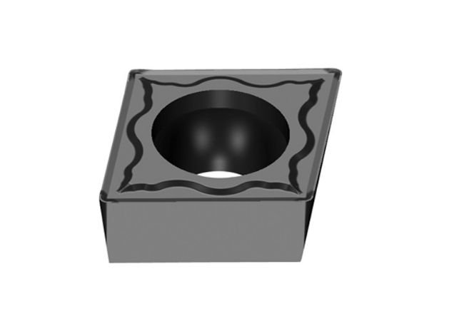
ESTool CCMT Insert
Description:
ESTool CCMT Insert, 80 Degree, Single-sided CCMT Carbide Turning Inserts with different of molded chipbreaker type. Screw on style insert. Ideal for semi-finishing and finishing on a wide range of materials.
Feature:
- 80 degree diamond, single sided
- Positive rake
- 7° side clearance
- 6mm, 8mm, 9mm or 12mm cutting edges
- Available in a range of radius for finishing, general purpose and rough turning
- Coating: PVD or CVD
- Material?: Tungsten Carbide
| ESTool CCMT Insert |
| HF |
| Insert shape |
?Type |
Size (mm) |
| L |
ΦI.C |
S |
Φd |
r |
| HF? Finishing |
CCMT060202-HF |
6.4 |
6.35 |
2.38 |
2.8 |
0.2 |
| CCMT060204-HF |
6.4 |
6.35 |
2.38 |
2.8 |
0.4 |
| CCMT060208-HF |
6.4 |
6.35 |
2.38 |
2.8 |
0.8 |
| CCMT09T302-HF |
9.7 |
9.525 |
3.97 |
4.4 |
0.2 |
| CCMT09T304-HF |
9.7 |
9.525 |
3.97 |
4.4 |
0.4 |
| CCMT09T308-HF |
9.7 |
9.525 |
3.97 |
4.4 |
0.8 |
| CCMT120404-HF |
12.9 |
12.7 |
4.76 |
5.56 |
0.4 |
| CCMT120408-HF |
12.9 |
12.7 |
4.76 |
5.56 |
0.8 |
| EF |
| Insert shape |
?Type |
?Size (mm) |
| L |
ΦI.C |
S |
Φd |
r |
| EF? Finishing |
CCMT060202-EF |
6.4 |
6.35 |
2.38 |
2.8 |
0.2 |
| CCMT060204-EF |
6.4 |
6.35 |
2.38 |
2.8 |
0.4 |
| CCMT09T302-EF |
9.7 |
9.525 |
3.97 |
4.4 |
0.2 |
| CCMT09T304-EF |
9.7 |
9.525 |
3.97 |
4.4 |
0.4 |
| CCMT09T308-EF |
9.7 |
9.525 |
3.97 |
4.4 |
0.8 |
| CCMT120404-EF |
12.9 |
12.7 |
4.76 |
5.56 |
0.4 |
| CCMT120408-EF |
12.9 |
12.7 |
4.76 |
5.56 |
0.8 |
| HM |
| Insert shape |
?Type |
?Size (mm) |
| L |
ΦI.C |
S |
Φd |
r |
| HM? Semi-finishing |
CCMT060204-HM |
6.4 |
6.35 |
2.38 |
2.8 |
0.4 |
| CCMT060208-HM |
6.4 |
6.35 |
2.38 |
2.8 |
0.8 |
| CCMT09T304-HM |
9.7 |
9.525 |
3.97 |
4.4 |
0.4 |
| CCMT09T308-HM |
9.7 |
9.525 |
3.97 |
4.4 |
0.8 |
| CCMT120404-HM |
12.9 |
12.7 |
4.76 |
5.56 |
0.4 |
| CCMT120408-HM |
12.9 |
12.7 |
4.76 |
5.56 |
0.8 |
| CCMT120412-HM |
12.9 |
12.7 |
4.76 |
5.56 |
1.2 |
| EM |
| Insert shape |
?Type |
?Size (mm) |
| L |
ΦI.C |
S |
Φd |
r |
| EM? Semi-finishing |
CCMT060204-EM |
6.4 |
6.35 |
2.38 |
2.8 |
0.4 |
| CCMT060208-EM |
6.4 |
6.35 |
2.38 |
2.8 |
0.8 |
| CCMT09T304-EM |
9.7 |
9.525 |
3.97 |
4.4 |
0.4 |
| CCMT09T308-EM |
9.7 |
9.525 |
3.97 |
4.4 |
0.8 |
| CCMT120404-EM |
12.9 |
12.7 |
4.76 |
5.56 |
0.4 |
| CCMT120408-EM |
12.9 |
12.7 |
4.76 |
5.56 |
0.8 |
| CCMT120412-EM |
12.9 |
12.7 |
4.76 |
5.56 |
1.2 |
| HR |
| Insert shape |
?Type |
?Size (mm) |
| L |
ΦI.C |
S |
Φd |
r |
| HR Roughing |
CCMT060204-HR |
6.4 |
6.35 |
2.38 |
2.8 |
0.4 |
| CCMT060208-HR |
6.4 |
6.35 |
2.38 |
2.8 |
0.8 |
| CCMT09T304-HR |
9.7 |
9.525 |
3.97 |
4.4 |
0.4 |
| CCMT09T308-HR |
9.7 |
9.525 |
3.97 |
4.4 |
0.8 |
| CCMT120408-HR |
12.9 |
12.7 |
4.76 |
5.56 |
0.8 |
| CCMT120412-HR |
12.9 |
12.7 |
4.76 |
5.56 |
1.2 |
Hot Sales Products:
Carbide Drilling Inserts
|
CCGT Insert
|
RCGT Insert
|
CNC Inserts
|
Coated Inserts
The Carbide Inserts Website: https://www.estoolcarbide.com/product/wnmg-pressing-cermet-inserts-p-1201/
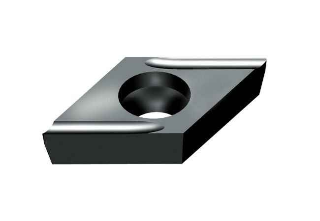
ESTool DCGT Insert
Description:
ESTool DCGT Insert, 55° Rhombic Insert with 7° Positive Clearance For Finishing?Applications.
Feature:
- 55° Rhombic insert
- Single sided
- Positive rake
- 7° side clearance
- 7mm or 11mm cutting edges
- Available in a range of radius for finishing, general purpose and rough turning
| ESTool DCGT Insert |
| USF |
| Insert shape |
?Type |
?Size (mm) |
| L |
ΦI.C |
S |
Φd |
r |
| USF Precision Machining |
DCGT0702005R-USF |
7.8 |
6.35 |
2.38 |
2.8 |
0.05 |
| DCGT070201R-USF |
7.8 |
6.35 |
2.38 |
2.8 |
0.1 |
| DCGT070202R-USF |
7.8 |
6.35 |
2.38 |
2.8 |
0.2 |
| DCGT11T301R-USF |
11.6 |
9.525 |
3.97 |
4.4 |
0.1 |
| DCGT11T302R-USF |
11.6 |
9.525 |
3.97 |
4.4 |
0.2 |
| USF |
| Insert shape |
?Type |
?Size (mm) |
| L |
ΦI.C |
S |
Φd |
r |
| USF Precision Machining |
DCGT0702005L-USF |
7.8 |
6.35 |
2.38 |
2.8 |
0.05 |
| DCGT070201L-USF |
7.8 |
6.35 |
2.38 |
2.8 |
0.1 |
| DCGT070202L-USF |
7.8 |
6.35 |
2.38 |
2.8 |
0.2 |
| DCGT11T301L-USF |
11.6 |
9.525 |
3.97 |
4.4 |
0.1 |
| DCGT11T302L-USF |
11.6 |
9.525 |
3.97 |
4.4 |
0.2 |
| SF |
| Insert shape |
?Type |
?Size (mm) |
| L |
ΦI.C |
S |
Φd |
r |
| SF Precision Machining |
DCGT070202-SF |
7.8 |
6.35 |
2.38 |
2.8 |
0.2 |
| DCGT070204-SF |
7.8 |
6.35 |
2.38 |
2.8 |
0.4 |
| DCGT070208-SF |
7.8 |
6.35 |
2.38 |
2.8 |
0.8 |
| DCGT11T302-SF |
11.6 |
9.525 |
3.97 |
4.4 |
0.2 |
| DCGT11T304-SF |
11.6 |
9.525 |
3.97 |
4.4 |
0.4 |
| DCGT11T308-SF |
11.6 |
9.525 |
3.97 |
4.4 |
0.8 |
Hot Sales Products:
Carbide Milling Inserts
|
Surface Milling Inserts
|
TCGT Insert
|
TNGG Insert
|
Lathe Inserts
The Carbide Inserts Website: https://www.estoolcarbide.com/product/snmg-carbide-inserts-for-stainless-steel-turning-inserts-p-1186/
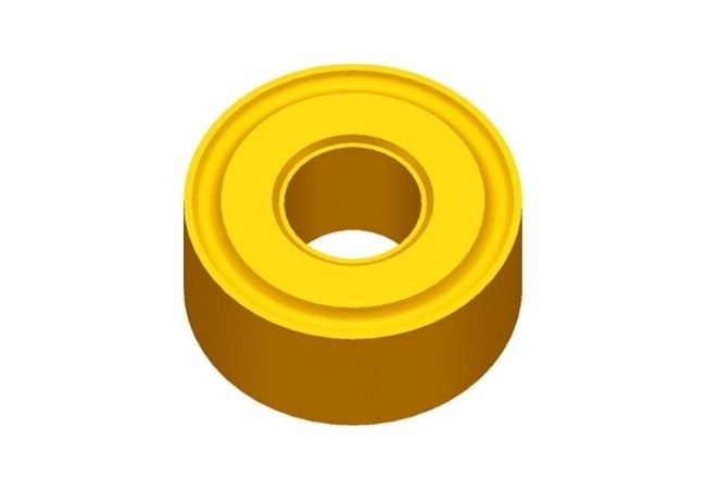
ESTool RNMG Insert
Description:
ESTool RNMG Insert, Double-sided Round Negative Carbide Inserts?for medium and rough profiling.
Feature:
- Negative round common-type inserts with chipbreaker
- For medium roughing applications
| ESTool RNMG Insert |
| Insert shape |
Type |
?Size (mm) |
| L |
ΦI.C |
S |
Φd |
r |
| Through slot |
RNMG120400 |
12.7 |
12.7 |
4.76 |
5.16 |
|
Hot Sales Products:
Carbide Grooving Inserts
|
Cast Iron Inserts
|
Milling inserts
|
Cermet Inserts
|
DNMG Insert
|
APKT Insert
The Carbide Inserts Website: https://www.estoolcarbide.com/product/dnmg-carbide-inserts-for-stainless-steel-turning-inserts-p-1185/